Yard-man YM70SS User Manual
Browse online or download User Manual for Gardening equipment Yard-man YM70SS. Yard-Man YM70SS User Manual
- Page / 52
- Table of contents
- BOOKMARKS
- Operator’s Manual 1
- SAVE THESE INSTRUCTIONS 2
- KNOW YOUR UNIT 4
- ASSEMBLY INSTRUCTIONS 5
- Starting 7
- Position 7
- OPERATING INSTRUCTIONS 8
- Single Line Installation 10
- SplitLine™ Installation 10
- WARNING: 11
- SPECIFICATIONS 14
- Yard-Man LLC 16
- Manuel de L'utilisateur 17
- CONSERVEZ CES CONSIGNES 18
- INSTRUCTIONS DE MONTAGE 21
- Position de 23
- MODE D’EMPLOI 24
- AVERTISSEMENT : 25
- ENTRETIEN ET RÉPARATIONS 25
- MISE EN GARDE : 28
- CARACTÉRISTIQUES 30
- REMARQUES 31
- Manual del Operador 33
- GUARDE ESTAS INSTRUCCIONES 34
- CONOZCA SU UNIDAD 36
- INSTRUCCIONES DE ENSAMBLE 37
- Posición de 39
- Arranque 39
- INSTRUCCIONES DE OPERACIÓN 40
- AVERTENCIA: 41
- ESPECIFICACIONES 46
- 2-CYCLE GAS TRIMMER 50
Summary of Contents
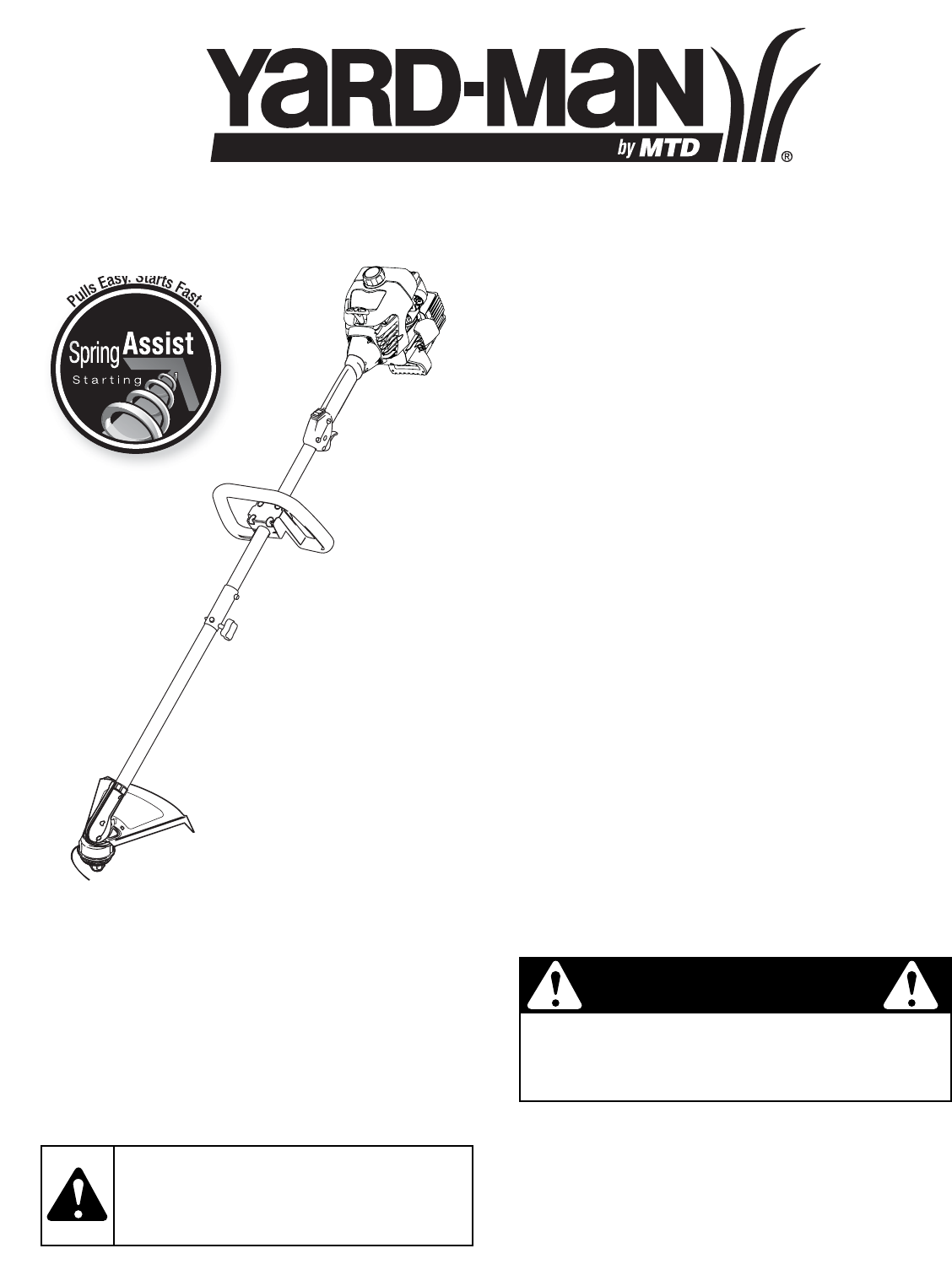
Operator’s ManualPullsEasy.StartsFast.StartingTM2-Cycle Gasoline TrimmerYM70SSSAVE THESE INSTRUCTIONSFor service call 1-800-800-7310 in the United Sta
10Fig. 22Fig. 18NOTE: SplitLine™ can only be used with the inner reel with theslotted holes. Single line can be used on either type ofinner reel. Use
11MAINTENANCE & REPAIR INSTRUCTIONSCleaning the Air FilterClean and re-oil the air filter every 10 hours of operation. It is animportant item to m
12Check Fuel MixtureOld and/or improperly mixed fuel is usually the reason forimproper unit performance. Drain and refill the tank with fresh,properly
13TROUBLESHOOTINGIf further assistance is required, contact your authorized service dealer. CAUSE ACTIONAir filter is plugged Replace or clean the air
14ENGINE**All specifications are based on the latest product information available at the time of printing. We reserve the right to make changesat any
15NOTES
MANUFACTURER’S LIMITED WARRANTY FOR:No implied warranty, including any implied warranty ofmerchantability or fitness for a particular purpose, applies
Manuel de L'utilisateurPullsEasy.StartsFast.StartingTMDésherbeuse à gaz à 2-tempsYM70SSCONSERVEZ CES INSTRUCTIONSObtenez la liste des concessionn
F2CONSIGNES DE SÉCURITÉLISEZ TOUTES LES INSTRUCTIONS AVANT UTILISATION• Lisez soigneusement cette notice. Familiarisez-vous avec lescommandes et la ma
F3CONSIGNES DE SÉCURITÉSYMBOLES DE SÉCURITÉ ET INTERNATIONAUXCe manuel de l'utilisateur décrit les symboles et pictogrammes de sécurité et intern
2READ ALL INSTRUCTIONS BEFORE OPERATING• Read the instructions carefully. Be familiar with the controlsand proper use of the unit.• Do not operate thi
F4FAMILIARISEZ-VOUS AVEC VOTRE APPAREILProtecteurd'accessoire decoupeBouchon du carburantManettedes gazPoignée en DAccessoire de coupeBoîtierd&ap
F5La poignée en D peut être préinstallée sur certains appareils.Dans ce cas, il suffit de desserrer les vis et ajuster la poignéeen fonction de l&apos
F6FONCTIONNEMENT DU EZ-LinkMCLe système EZ-LinkMCpermet d'utiliser ces accessoiresoptionnels :Cultivateur . . . . . . . . . . . . . . . . . . .
F7Commande Marche/ArrêtManette des gazFig. 11Position dedémarrageArrêt (O)Démarrage/Allumage (I)Manettedes gazFig. 9DésherbeuseÉquipée deSpring Assist
F8REMARQUE : Ne posez pas la tête de butée sur le sollorsque l’appareil est en marche.Le fil peut se briser dans les cas suivants :• Happement de corp
F9REMARQUE : certaines procédures d'entretien nécessitent descompétences ou des outils particuliers. Si vous n'êtespas sûr de pouvoir les en
F10REMARQUE : utilisez toujours la bonne longueur de fil lorsquevous posez le fil sur l'appareil. Le fil risque de ne passe dérouler correctement
F11Filtre à airFig. 25Fig. 26Fig. 27Fig. 28Protection du filtredans le silencieuxRéinstallation du filtre à air/couvercle du silencieux1. Placez le fi
F12Fig. 30ENTRETIEN ET RÉPARATIONSAVERTISSEMENT : il se peut que l'accessoire decoupe tourne pendant le réglage de la vitesse deralenti. Portez
F13DÉPANNAGESi vous avez besoin d'aide, contactez votre concessionnaire agréé. CAUSE SOLUTIONPrésence d'huile dans la tête de coupe Nettoye
3RULES FOR SAFE OPERATIONSAFETY AND INTERNATIONAL SYMBOLSThis operator's manual describes safety and international symbols and pictographs that m
F14* Toutes les spécifications contenues dans ce manuel tiennent compte des dernières informations techniques disponibles au moment de mettre souspres
F15REMARQUES
F16GARANTIE LIMITÉE DU FABRICANT POUR:Aucune garantie implicite, y compris toute garantie de valeurmarchande ou d’adaptation à une fin particulière, n
Manual del OperadorPullsEasy.StartsFast.StartingTMRecortador de 2 Tiempos a GasolinaYM70SSCONSERVE ESTAS INSTRUCCIONESLlame 1-800-800-7310 en EE.UU. o
E2LEA TODAS LAS INSTRUCCIONES ANTES DE OPERAR LAUNIDAD• Lea las instrucciones cuidadosamente. Familiarícese conlos controles y el uso adecuado de la
E3NORMAS PARA UNA OPERACIÓN SEGURASIMBOLOS DE SEGURIDAD E INTERNACIONALESEste manual del operador describe los símbolos y figuras de seguridad e inter
E4CONOZCA SU UNIDADProtecciónaccesoria decorteTapa del combustibleGatillo delreguladorManija en DAccesorio de corteBastidor deengranajesManjo del ejeB
E5Fig. 1Fig. 2(4) TornillosManija en DAbrazadera inferiorMínimo de 15,24 cm (6 pulgadas)Bastidordel ejeMango del eje3. Sostenga cada tuerca hexagonal
E63. Gire la perilla en sentido horario para ajustarla (Fig. 8).OPERACION DEL SISTEMA EZ-Link™ El sistema EZ-Link™ le permite el uso de estos accesori
E7Control del reguladorFig. 11Posición deArranqueArranque/Encendido (I)Parado/Apagado (O)Control delreguladorFig. 9Spring AssistStarting™ RecortadorEq
4KNOW YOUR UNITCutting AttachmentShieldFuel CapThrottleControlD-HandleCutting AttachmentGear HousingShaft GripPrimer BulbBlue ChokeLeverSpark PlugEngi
E8COMO SOSTENER EL RECORTADORAntes de operar esta unidad, párese en posición de operación(Fig. 12). Verifique lo siguiente:• El operador tiene protecc
E9PROGRAMA DE MANTENIMIENTOEstos procedimientos requeridos para el mantenimiento debenser realizados con la frecuencia indicada en la tabla. Deben ser
E10Fig. 22Fig. 23Instalación de la línea individualLea la instalación de la línea SplitLine™ en el paso 86. Tome aproximadamente 6 m (20 pies) de nuev
E11INSTRUCCIONES DE MANTENIMIENTO Y REPARACIÓNTornillosTornillosPalanca azuldel obturadorFig. 24importante. No mantener debidamente su filtro de aire
E12INSTRUCCIONES DE MANTENIMIENTO Y REPARACIÓNNOTA: El accesorio de corte no debe girar mientras elmotor está en marcha lenta. 3. Si el accesorio de c
E13RESOLUCIÓN DE PROBLEMASSi necesita asistencia adicional, comuníquese con su proveedor de servicio autorizado. CAUSA ACCIÓNEl cabezal de corte tiene
E14*Toda las especificaciones contenidas en este manual se basan en la información más reciente disponible en el momento de impresióndel manual. Nos r
E15NOTAS
E16NOTAS
E17NOTAS
5ASSEMBLY INSTRUCTIONSOn some units, the D-handle may be pre-installed, requiringonly loosening screws and some adjustment. If this is the case,go to
E18PARTS LISTREPLACEMENT PARTS - MODEL YM70SS2-CYCLE GAS TRIMMER12381012345761113144850205118151617192223242527322834332621414743453094644394931293839
E19PARTS LISTREPLACEMENT PARTS - MODEL YM70SS2-CYCLE GAS TRIMMERItem Part No. Description1 753-04234 Throttle Housing Assembly (includes 2-4)2 753-041
E20GARANTÍA LIMITADA DEL FABRICANTE PARA:Ninguna garantía implícita es aplicable, incluyendocualquier garantía implícita de comerciabilidad o idoneida
6ASSEMBLY INSTRUCTIONSFor decorative trimming/edging with the line head cuttingattachment, lock the release button of the cutting attachmentinto the 9
7STARTING INSTRUCTIONSFig. 9Throttle ControlFig. 11Start/On ( I )Stop/Off (O)ThrottleControlStartingPositionTrimmerEquipped WithSpring AssistStarting
8NOTE: Do not rest the Bump Head™ on the ground while theunit is running.Some line breakage will occur from:• Entanglement with foreign matter• Normal
9MAINTENANCE & REPAIR INSTRUCTIONSMAINTENANCE SCHEDULEPerform these required maintenance procedures at thefrequency stated in the table. These pro
Related products and manuals for Gardening equipment Yard-man YM70SS
 (44 pages)
(32 pages)
(44 pages)
(32 pages)

 (56 pages) (16 pages)
(20 pages)
(56 pages) (16 pages)
(20 pages)
© 2020, manymanuals.com. All rights reserved. | 2.086 s |
 Manymanuals.com
 Manymanuals.de
 Manymanuals.fr
 Manymanuals.it
 Manymanuals.pl
 Manymanuals.cz
 Manymanuals.es
 Manymanuals-pt.com
Comments to this Manuals